Skip to content

6n2 1.4 16v lambda sensor dtc wont go away :)

Featured Replies

hi all, i have a 2000 6n2 1.4 16v AUA engine, i have almost replaced all the sensor in the engine now and the majority of the error codes have gone and its running alot better but its still shaking badly. the lambda sensor is new and the old one had only done about 500 miles at most and worked fine on the old engine (changed to AUA from AUD) - but these codes keep coming up,

17589 - Linear 02 sensor: Reference Voltage

P1181 - 35-00 - Open Circuit

17525 - Oxygen (Lambda) Sensor Heating: B1 S1

P1116 - 35-00 - Open Circuit

17604 - Oxygen (Lambda) Sensor Heater Circuit: B1 S!

P1196 - 35-00 - Electrical Malfunction

can some one please tell me what the reference voltage is? is that the power feed from the ECU?

also, what is an electrical malfunction?

to me it seams like its an earthing problem, where is the lambda circuit earthed?

also, i read somewhere that the sensor is grounded by the exhaust pipe, but when i tested there was no ground at all, but on the sensors body there was?

also read that its common for the wires to break near the plug, i have taken the sheithing off for a good few inches and there are no breaks i can see - i have the plug from the old loom, so if need be i could use that?

also, may be relevant, there was a similar error for the rear sensor, which i also replaced with a new sensor and this has since gone.

any help on this would be really appreciated.

thanks

  • Replies 24
  • Views 21.9k
  • Created
  • Last Reply

Top Posters In This Topic

Check the wiring from the disconnects back to the ECU, the +Ve supply to the heater should be there at all times the ignition is ON, the ECU switches the ground on/off as required and its via this it measures the current going through the heater element to give the heater fault codes.

Have a look at the posting about GTi fuel consumption, there is lots of info regarding VCDS readouts for the voltages expected etc.

Chk your PM file :)

I suggest that you follow the diagnostic process in the attached document, and wiring diagram. It's only a 10 minute job to check the wiring from the lambda connector back to the ECU, there's no earth on the lambda circuit, other than through the ECU internally, that I can see. On my car only one of the 6 wires was actually intact and the wire itself deteriorates internally. These should be for your AUA engine, I don't know if there is a difference between the looms for an AUA and AUD engine, I'm sure Nige will

S1_lambda_sensor_wiring.pdfchecking_S1_lambda_sensor.pdf

A shaking engine seems more like a misfire / single cylinder fault rather than a fault which affects all cylinders, how do you reproduce the fault ?

  • Author

hi,

didnt realise you posted on here, i was busy on your thread :)

that diagram shows that the colours are correct, but its still strange to me that the two thicker wires are in different places? in my mind and now in the diagram they are for the heater circuit, so that must mean the sensors are different? baffling really.

but i know now the pins are correct, so i will replace the metal pins with new ones, and make sure they arent broken.

i think there is an actual engine fault also, rather then just an electronic one but these errors keep coming up.

-what do you mean by reproduce the fault?

thanks for the help guys :)

  • Author

i went ahead and looked at the lambda connector to change the metal connectors, and when i removed them from the plastic housing, i found that 3 wires were almost completely broken. so i changed all 6 connectors and used the other plastic part from my other loom.

all back together and started it, and initally it was running lovely and sounded as though it was on fast idle, but then after a few seconds the revs dropped and it started shaking and the engine light came on again, but this time it only came up with the reference voltage one

from the diagram it shows pins 4 and 5 going in to the sensor and 3 and 6 coming out, so am i right in saying the voltage that is showing at either 4 or 5 isn't equivalent to the stored "reference" voltage in the ecu?

another question is, theoretically if the inlet timing was off by say 1 tooth, the engine would obviously shake, but would it throw up a lambda code?

i ask because initally i had AUB cams in this engine, but swapped back to the AUA ones, but while doing so i managed to damage the inlet cam pulleys key (bit to locate it to cam), it tightened down okay so i thought nothing of it, but i am thinking this is the route of the rough running, but I'm not sure if the two issues are linked.

the engine was completely rebuilt before i fitted it, it was done by me and checked by three other mechanics, and the list of new parts after it was fitted is very long, in hindsight i probably should have just bought an engine and loom from a breakers that all matched up and had a warranty, but i thought i should spend the money on reconditioning this, but you live and you learn :(

When I was checking my wiring I hand drew a rectangle for the connector plug, placed the pin numbers on the inside of the box and the wire colours, thickness and ECU terminal connection on the outside.

If you do that I think you'll see that the thick wires are opposite each other in positions 1 and 2. That makes sense as those are the wires that carry the current for the heater circuit. You can then easily test the continuity to the other pins. Pin 2 carries the feed for the heater circuit from the fuel pump relay, so you should start the car with the pin disconnected and confirm 12v is present when the car is running. As you have rewired the connector I suspect that's all OK now, and perhaps confirmed by the absence of the lambda error codes.

When I asked about reproducing the fault, I was wanting to try and understand what circumstances caused the shudder, as that seemed to be an engine imbalance, probably caused by a single cylinder problem. You could start the engine and remove either spark or fuel from one cylinder at a time. If the problem get's worse, you know that cylinder is working. Looking up error code 17589, that seems to be a lambda problem so I suggest that you recheck the wiring and the reference voltage as in this document checking_s1_probe.pdf Other possible causes of this problem are ignition cables, spark plugs and misfire detection (knock sensor). You can look at measuring blocks in 014 to 028 in vagcom for further information

Have you rechecked the valve timing ? When I had my emission issue it was suggested to me that having the cam timing out could cause the emissions problem, as could having a sticking valve, which is why I did compression and leak tests. Given that this is a freshly rebuilt engine I doubt it's going to be a sticking valve. Note however that these suggestions were for the emissions problem, not a cause of a faulty lambda reading or error.

Daft question time. You do have the right ECU for the AUA engine and have you cleared all the learnt values in the ECU to allow it to re-adapt to the freshly rebuilt engine. I don't know enough to be able to say if your original AUD ECU will run an AUA engine properly.

Hope that helps

  • 5 weeks later...
  • Author

Uber lare relly time.

I managednto gdt the engine running properly and it now runs perfectly. It was the inlet cam pilley that was damaged. The locating pin that goes into the cam was almost completely gone. So the cam was almost self adjustijg itself as I revved it. Then I found out that number 1 and 4 injector wer not working at all. Changed them from my ever growing crate of spares and its spot om.

however, there is now a code that does not go away. Its reference voltage - open circuit.,

from what I can tell from yet more google bashing the only cure is to change the sensor, but as the one I have is a new one, I am left with thinking either the wires at the plug are still erong, or they are broken somewhere between the ecu and plug.

I have the elsa diagrams for this loom so I am going to check each pin and wire tomorrow.

Is there any way of bench testing the sensors ? I haven't ben able to find any info as I imagine the makers dont want you to test it only buy a (very expensive) new one.

And yes all the wiring and ecu etc is the correct one for the engine, I swapped everything over from a donor car. BUT I did not have any history and didnt hear it running etc as it was taken apart for me, this was one of the many mistakes on my ever growing list :)

Thanks for all the help

What's the fault code?

I managednto gdt the engine running properly and it now runs perfectly. It was the inlet cam pilley that was damaged. The locating pin that goes into the cam was almost completely gone. So the cam was almost self adjustijg itself as I revved it.

Delighted to hear you are making progress. It's funny i was helping a mate out with a Ford zetec engine which had siezed. The cam pulley on those are only held in place by friction from the mounting bolt as there is no keyway or alignment pin and his had slackened enough to allow slippage.

if you can post the error code i think you'll get some more help

Haha nightmare Ford engines. pulleys off to get the cams out, cams out to get the head off... Safe to say not bothered with one since!

  • Author

Thanks for the replies,

Gbd8512- thanks for the link, it looks like I'd need an oscilloscope to test them, which I don't :(

I was thinking more like a resistance I could check across pins on the snesor etc.

You would be surprised at how many people start changing there timing belt on zetec engines and get stuck, my mechanic friend is always finishing them for people as you have to lock the crank and the cam in a certain way.

Update, today I got playing with a multi meter and checking pins between ecu and connectors, didn't get far as I found the earth wires at the ecu had a high resistance and was showing ~5v so I tried to undo the nut and it snapped clean off meaning it was barely connected, so I drilled a hole and clean the metal and put a bolt through the metal and ran a new earth on the other side down to the gearbox earth point. It showed a decimal resistance and 12.3v, started it and it sounded better (usually it starts fine then idle drops) but that's as far as I got with it today, so tomorrow I will get vagcom up and see what it's saying.

But to me this looks like it's the fault as if the ecu voltage was low then the "reference" voltage will in fact be wrong and thus throw up a code.

Edited by dixy

You can use vagscope part of VCDS/Vagcom to see the output voltages etc

  • Author

update-

i ran vagcom and this is what came up at first, as expected really as i hadnt cleared them yet -

4 Faults Found

17589 - Linear O2 Sensor; Reference Voltage
P1181 - 35-10 - Open Circuit - Intermittent
17524 - Oxygen (Lambda) Sensor Heating; B1 S1
P1116 - 35-00 - Open Circuit
17604 - Oxygen (Lambda) Sensor Heater Circuit: B1 S1
P1196 - 35-00 - Electrical Malfunction
17953 - Throttle Valve Controller
P1545 - 35-10 - Malfunction - Intermittent

Readiness: 1010 0101

i then cleared them and immediately this came up-

2 Faults Found

17589 - Linear O2 Sensor; Reference Voltage
P1181 - 35-00 - Open Circuit
17524 - Oxygen (Lambda) Sensor Heating; B1 S1
P1116 - 35-00 - Open Circuit

Readiness: N/A

so there goes the tain on my parade :(

this got me thinking that itwas the wiring being wrong, ie pins intthe wrong places.

here is the elsawin diagram of the S1 connector:

Untitled_zpsd9fed643.png

so, what got me thinking last time was that the heater wires seamed in the wrong place, for starters as i am certain they are the centre two pins on the sensors plug, so 3 and 5. diagram (and plug on the car) show 1 and 2 as heater wiress.

7057scon_zps12084d17.gif

after a bit of googling, i found this diagram (really isnt that much info on these?) which are exactly as its wired on the sensor. showing 3 and 4 as heater. also 2 and 6 are joined together, which on the elsawin diagram looks to be pins 3 and 6, which are totally off even if they are numbered backwards. so i guess from here i have 2 wires left over 1 and 5 which from the looks of it are pins 4 and 5 on the elsa diagram.

question is, what goes where? whihc wires from the ecu correspond to IP,VS and VS/IP - a total assumption at this stage would be that the VS/IP is the reference wire?

any help on this would be really appreciated as i think i am out of my depths on this one now :sorry:

- also, i did look at vagscope but it reads 0 for all the front lambda signals i could find, i guess it shuts off power when a fault code comes up?

Edited by dixy

If I recall correctly, the wiring of the 6 pin plug varies between engine codes so be careful with internet sources.

The picture you have above is the same as the attachment in post 3 of this thread. When I had problems with my wiring I manually drew the connector on a piece of paper and wrote on the colours, wire thickness and connection for each terminal, then made sure that the connector block was the same as the drawing and the wires trace back to the ECU plug correctly. You have noticed that the pin numbers are written on the side on the connector plug ?

For your car I would agree that pins 1 and 2 are the heater wires. You can see that because of the terminal pins and the use of thicker wire

Have a read of the lambda probe diagnostic document again......... the more you have done the more sense it will make, at least it did for me :smile:

Edited by 937carrera

  • Author

i took that screen shot from elsawin and yes it is the same as the one you posted even the ecu pins are the same.

yes i put the pins back into the plug as per the diagram using the number on the plastic plug, but thats where i am doubtful, as you said pin 1 and 2 are for the heater element, but on the actual sensor it is 3 and 4 for the heating, so even if i go it wrong those pins would be in the same place as they are in the middle, but the diagram is saying they should be at 1 and 2. and this is the same for all the polo variations i can find which tells me that the sensors i have are wrong.

so for example as it is wired now (correct to diagram above) it is sending heater voltage through the sensors vs and ip lines and no doubt giving the ecu heater voltage through the only pin that is in the correct place ( pin 5) which I'm thinking is the reference line?

somehow i totally missed those sensor testing guides you posted,i have one sensor here on my desk and it has continuity between 3 and 4 but not between 3 and 5 as it says. so this proves the heating is okay in this sensor.

also in that guide it mentions proving the wiring between the 6 pin plug and the fuel pump relay, this again sent alarm bells ringing because when i did the engine swap i found that the fuel pump relay contact had over heated ad come away from the relay, i cant really recall what i did about it but i am damn sure going to check now.

If you have Elsawin that should be a big help. I went back to your first post and looked at the engine codes. The lambda sensor wiring is different between the AUD and AUA engine codes. Here's the wiring diagram for a 2000 6n2 AUD enginewiring_s1_lambda_2000_aud.pdf, just for ease of reference.

On this, according to the wiring diagram, the heater is on pins 3 and 4, not 1 and 2 so it looks like you will have the right lambda sensor but will need to adapt the wiring to suit the wiring loom and ECU. That said, the diagnostic procedure says to test between pins 3 and 5 for continuity on the heater element which confuses me.

There's one other thing I noted when trying to find these wiring diagrams. Your photo says your car is a 1999 6N, but from what I can see the AUA was never fitted to the 6N, it was only fitted to the 6N2 from 2000 on. Perhaps you can confirm the car details again for us and if you also swapped the ECU and engine looms when doing the engine change

I think you may need help from someone with wider Polo knowledge than me. I have a decent understanding of the 6N2 Gti in particular, because that's what I own. Others will have a better idea of what changes you need to make when doing an engine swap, especially between versions.

Hope this helps

Edited by 937carrera

  • Author

i cant think why i didnt look at the aud wiring, it seems so obvious now. thank you so much

the diagram you linked to does make sens to me, and i think that this si the correct way it should be wired - at least in my case

I'm not saying vw are wrong, i may have a slightly different set of sensors :)

that said, yes the test procedure does say to test the middle two pins for continuity, so maybe they are wrong? there certainly seems to be ALOT of topics on lambda fualts with these sensors, and if the diagrams are wrong then perhaps the cars are also wired wrong meaning alot of vag cars may also be wired wrong ?

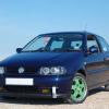
correct the picture does show a 6n, its my other halfs car the 6n is my daily car. it has been off the road for a long time and she is really getting on my case now so pressure is on to finally finish it.

i swapped some of the pins round and cleared the codes and then started it. checked the rediness and the lambda heating said passed, happy days. the above codes didnt come back on and the light stayed out. finally got a smile after doing something to this bloody car :)

however, now i have a different code, its

1 Fault Found

16555 - Fuel Trim; Bank 1
P0171 - 35-00 - System Too Lean

Readiness: 1010 0101

to me this is good news, it means that i am on the right track and at least the sensor is talking to the ecu so to speak.

i will go out now armed with the AUD wiring diagram and put the pins in those positions and see what happens.

thanks again buddy, you have been very helpful

I had that fault code on my GTi............. turned out to be that the 12v feed and lambda output connectors were swapped over. Read my tale of woes, and eventual solution here http://www.clubpolo.co.uk/forum/index.php?showtopic=334294&page=2

If you have vagcom you can watch the readings as the engine runs too

  • Author

spent almost the whole day outside trying to figure this stupid thing out.

i ended up starting over, so rechecked the wirres back to the ecu, and found three of them to have a higher resistance, so i ysed vw repair wires, with the pins already attached and replace the wire as far back as it would go. now they are all at almost 0 ohms pin to pin. i then put the pins in to what i now believe to be the right place, all back together and still says reference voltage too low. took the sensor out and found that the end of it is fouling on a blob of weld and has slightly crushed the end. cleaned it and swapped for the known good working one, still the same.

so i am led to believe that i have now fried both of these sensors, because i followed the wiring diagram and it put 12v through one side of the sensor, at least that's my theory.

i have found today that a lot of the wiring in the elsawin diagrams for this engine are wrong, the pins are correct but the colours are all off?

937carerra - can you please tell me if you have your heater wires at pins 1 and 2 (like on the diagram) ? and is this still working for you?

i know its a different loom and ecu, but as far as i can tell, all the bosch wideband sensors are wired in the same way, ie heater pin in the middle.

I reckon I must have spent 30+ hours trying to figure out how to get rid of all my error codes, involving swapping lambda sensors and catalytic converters to the point where they almost removed themselves upon instruction, so I do appreciate how you feel.

My GTi has the ARC engine so pins are as follows:

1 - Brown / Red, lambda sensor

2 - White / Red, lambda

3 - Green, Feed to heater circuit from fuel pump relay, should be 12v

4 - Green / Brown, "earth" side of heater circuit, connects to ECU

5 - Green / Grey, lambda

6 - Blue / Green, lambda

According to the wiring diagram pins 2 and 6 are joined within the connector, but I didn't see that in the real world. I'm not going to offer any view as to what function each of the lambda connectors does

You should see that the wiring for the ARC engine is the same (though different colours) as the AUD engine at the connector block, but the ECU connections are different due to the GTi being on Simos while the AUD is on Motronic. In this way it seems that the same Bosch sensor works for both engines, but a different one would be needed for the AUA engine, due to the heater being on pins 1 and 2.

May I suggest that you clear all the error codes and reset the learned values in the ECU before you progress further. In post 18 error 17589 had cleared, but it has now returned and 16555 has gone. It might have been reintroduced while you were doing the rewiring and is now a ghost ??

  • Author

thanks buddy,

lots of info there, had to stop reading twice as my brain hurt :) 1 thing i saw is a kind or cross section of the sensor, and it shows that at the tip of the sensor there is a cell going across it. I'm willing to be that this cell is now broken on my new sensor because it hit the blob of weld :(

i have alot better understanding of how the sensor works now, it would be great if i could find out what wires do what from the ecu, as then it would be a case of just matching them.

so your arc is wired the same as the aud, which is the correct way in my mind. i will now have to get another sensor, so i may as well see if there is a different type of sensor for this system, although the only variant i can see between part numbers is the cable length and if it comes with clips etc but so far all the pins are in the same place.

do you reckon the vw parts counter would be able to look into the diagram? maybe they an updated version. do they even give out that info? i haven't been to a vw dealer for a long time.

I personally wouldn't bother with the main dealer, unless you already know them well, and have a decent relationship with someone who will give you the correct answers.

Clear the codes, see where you are, and then if the error is still there get another sensor to try or put your hand in your pockets to buy a new one. I got my genuine Bosch one from EuroCarParts, though LambdaPower seem to know what they are on about, maybe give them a call ?

Just another thought, what readings are you getting from Vagcom

What are you seeing for

Lambda in block 001

Block 031

Block 036 voltage

Create an account or sign in to comment

Recently Browsing 0

  • No registered users viewing this page.

Account

Navigation

Search

Search

Configure browser push notifications

Chrome (Android)
  1. Tap the lock icon next to the address bar.
  2. Tap Permissions → Notifications.
  3. Adjust your preference.
Chrome (Desktop)
  1. Click the padlock icon in the address bar.
  2. Select Site settings.
  3. Find Notifications and adjust your preference.